
Context:
UIUC’s Robinson Lab conducts research that requires the studying of bees that are tagged with tiny 2x2mm “QR code” tags. Cameras are used to track the tags and analyze the behavior of bees (read more in this article by The Apiarist). Bee tagging is the process of applying these tags to the thoraxes of a large group of bees, and manually tagging a colony one by one can take researchers 12+ hours!
WaggleNet’s Bee Tagging team aims to build an automated system for tagging bees, which currently does not exist anywhere. By making this tool available to researchers, we hope to offer significant time savings and make bee tagging more feasible.
Bee Tagging is comprised of two sub-teams: Hardware and Software. Both sub-teams are deep in development of the first generation Bee Tagger, and we are nearing the point of testing a fully integrated system. Please keep reading to learn more about our work!
Hardware
This team is responsible for creating all the mechanical and electrical systems.
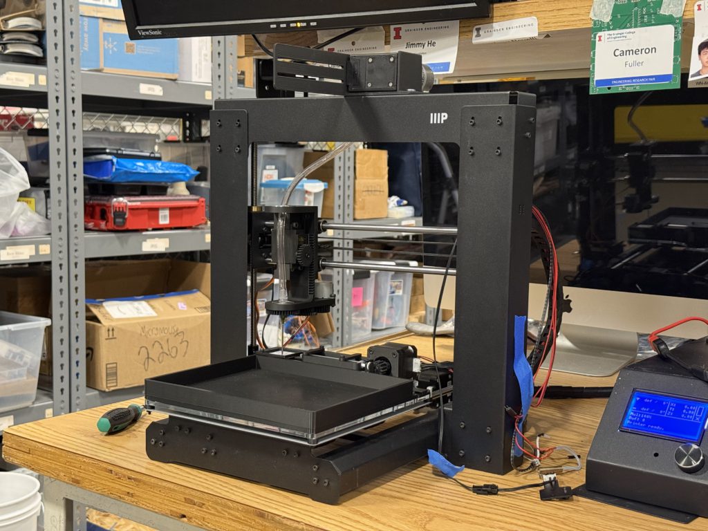
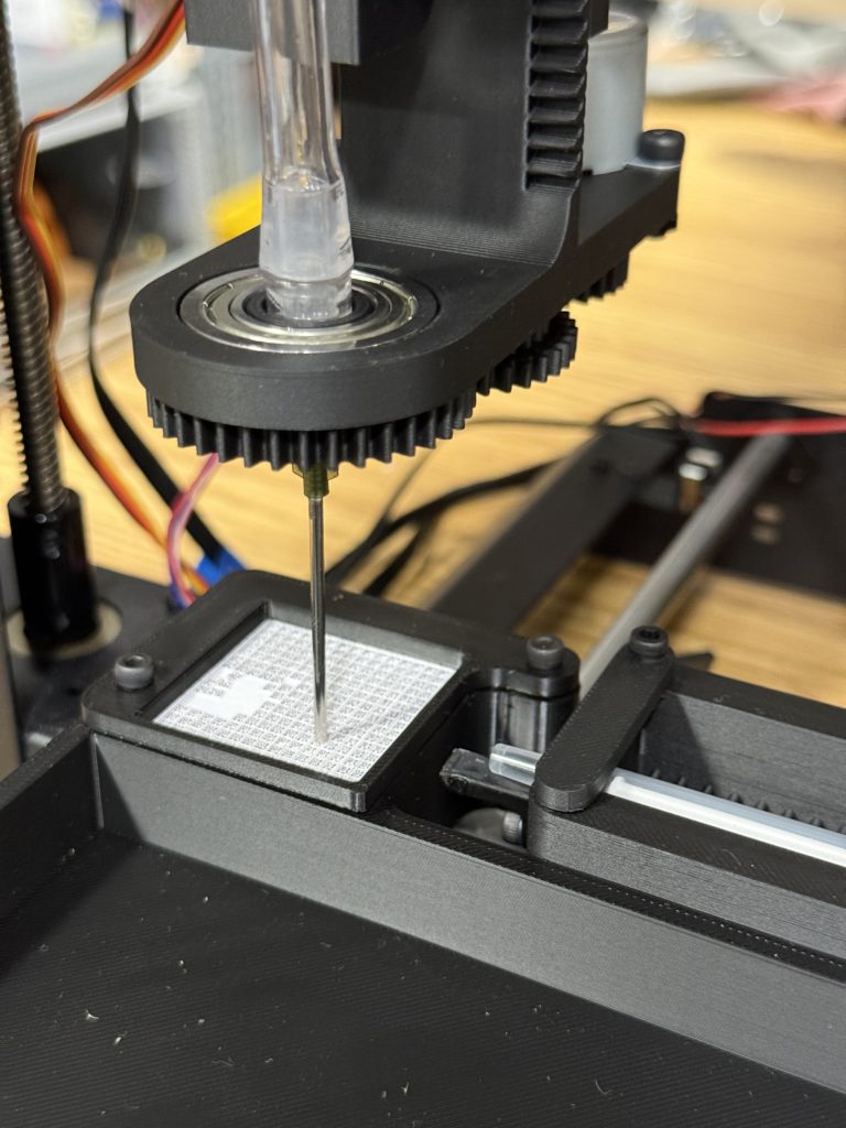
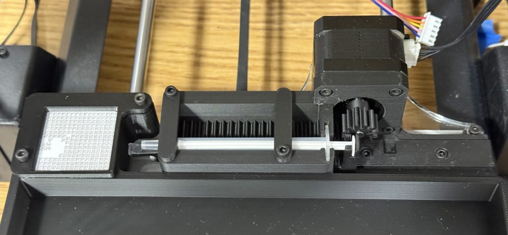
The philosophy behind Mk1 is to use what is available to us to make a minimum viable product on a fast timeline. Our goal is for both the hardware and software teams to learn from its creation, such that both have a solid foundation of experience entering Mk2 development. Our current design repurposes an old 3D printer for precise movement across an 8″ × 12″ platform. The Tag Applicator takes the place of the printer carriage and can pick and place tags with its vacuum nozzle. Additionally, a Glue Dispenser mechanism is mounted on the bed to supply glue for applying tags.
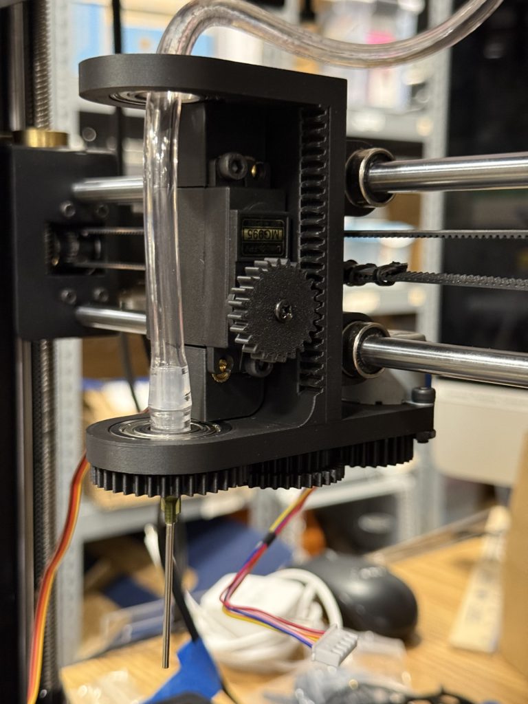
The Marlin-based 3D printer is an excellent base for use to build off of, as we can utilize its coordinate system by sending gCode commands directly via serial. We are working on establishing control over the mechanisms’ additional actuators with Raspberry Pi. These actuators include stepper, DC, and servo motors, which require different methods to connect. An outline of our control system is shown below:

Bee Tagging Hardware’s current objectives are to finish wiring and control of Mk1 actuators, fully integrate with software, and prototype a bee immobilizing system to be used for Mk2. As of Feb 2026, new member applications will open soon! Please apply if one of the following sounds like you:
- Mechanical designer capable of complex, moving mechanisms. Strong proficiency in Fusion360 for CAD, experience with design for 3D printing/3D printer hardware, assembly & hand tool skills. Strong communication skills in team environments, and enthusiasm + dedication towards the project 🙂
- Controls system designer with experience in Raspberry Pi, motor control, electrical wiring/circuit design, and Python programming. Experience with modifying 3D printers, Marlin, or Klipper is a bonus. Strong communication skills in team environments, and enthusiasm + dedication towards the project 🙂
Software
This team creates the software that detects bees in the camera feed and controls the motors to place the tag. The software pipeline consists of three processes:
- Detect the bee and thorax locations with neural networks.
- Convert pixel coordinate to location on the 3D printer bed.
- Generate a sequence of commands to place a tag on the bee.
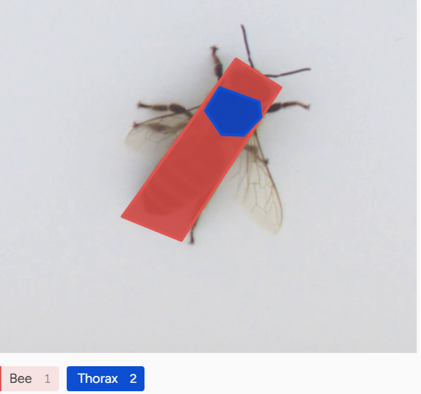
The computer vision system uses the DINO and YOLO neural networks to detect the location of bee thoraxes. DINO, a Vision Transformer, is a large pretrained vision model, allowing us to train the network with only a small number of labeled training images. YOLO is the standard object detector, which runs faster than DINO and can potentially output more accurate locations. Part of our work is comparing and integrating the two to create the most reliable detection algorithm.
We deploy the neural networks on Raspberry Pi, using a Python and PyTorch environment. We use acceleration techniques such as quantization to increase the inference speed.
After obtaining the pixel coordinates of the thorax, we need to convert them to a location on the 3D printer bed. We use a perspective transform from OpenCV’s Python API to perform the conversion. The process requires a manual calibration to determine the corners of the 3D printer bed.
Last, we generate the sequence of commands to pick up a tag, apply glue, and place it on the bee. We work closely with the hardware team in this step. We use G-code to control the 3D printer stepper motors, and PWM to control the servo and DC motors.