
Drafted by Anjali, Cameron, Nandini, and Norbert at WN’s Documentation-palooza 2k24
What is the purpose of our project?
To collect data from basic sensors (temperature, humidity, weight) that are placed in/around the beehive, and get this data to us as well as let beekeepers see live-ish measurements. This data will be stored on the logging device we can physically retrieve (or, soon, that will stream data to us wirelessly), and will also be read by beekeepers at the hive using the reading device without opening their hive.
Any data a beekeeper can get without opening the hive is useful, because opening up a hive can break propolis and sets back bees’ work about 3 days each time you open it.
We want to see the data ourselves because we want to do predictive analysis on the data for beekeepers, so they can know more about their hive than can learn about by inspection. When we have large amounts of data, we can do analysis on it to help the beekeeper understand what is going on inside the hive, including making predictions about what is going to happen.
Getting data to us: We would like to stream data wirelessly, but for now, we are just saving the data in a csv log file on our pico because that’s a good starting point.
Live display for beekeeper using the reading device: We want beekeeper to be able to know values, but we can’t have a display always on because it would draw too much power, so we store the most recent data in non-volatile memory (EEPROM) that can be read by the reading device the beekeeper brings to our setup. This reading device will connect to the EEPROM over I2C, read its values, and display it on a little screen for the beekeeper to read.
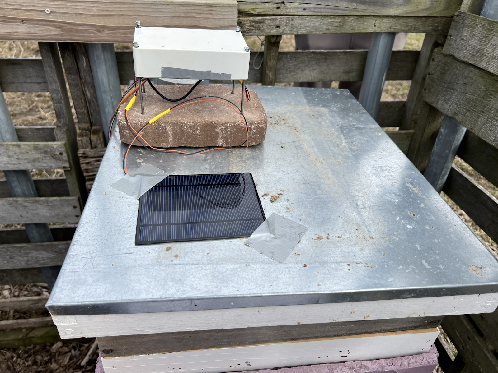
Solar power: Beehives are typically outside and not usually near an outlet, so we are using a solar panel and battery along with a battery manager to power the logging device.
Our design prioritizes ease of assembly, cheap cost, and durability.
How does it work?
The logging device sits on a hive, normally with no power. Periodically, the RTC sends a signal to a 555 timer, which in turn switches on a MOSFET that allows power to flow from the battery through the pico, powering it on. The pico then reads data from sensors, logs internally and writes into the EEPROM. When writing into the EEPROM, it erases everything before writing in the new data. Also, the data stored on the EEPROM is formatted text that can be displayed directly on the reading device’s display, to avoid formatting confusion on both ends. After the pico is done with everything, it sends an I2C message to the RTC to reset its alarm signal, which turns off the MOSFET and cuts power to the pico. This means that the pico is only on for a second or two every hour, reducing power consumption to near zero.
This PCB doc has more info about the power plan, but the plan has been modified since it was written. Modifications so far:
- The RTC needs to be reset with an I2C command in order for it’s alarm output to return to HIGH. Because of this, the 555 timer might not actually be necessary, as the pico could essentially just turn itself off when done. But for now we’re leaving it where the 555 timer will keep power on after the pico is totally done so the pico isn’t cut off in the middle of an instruction.
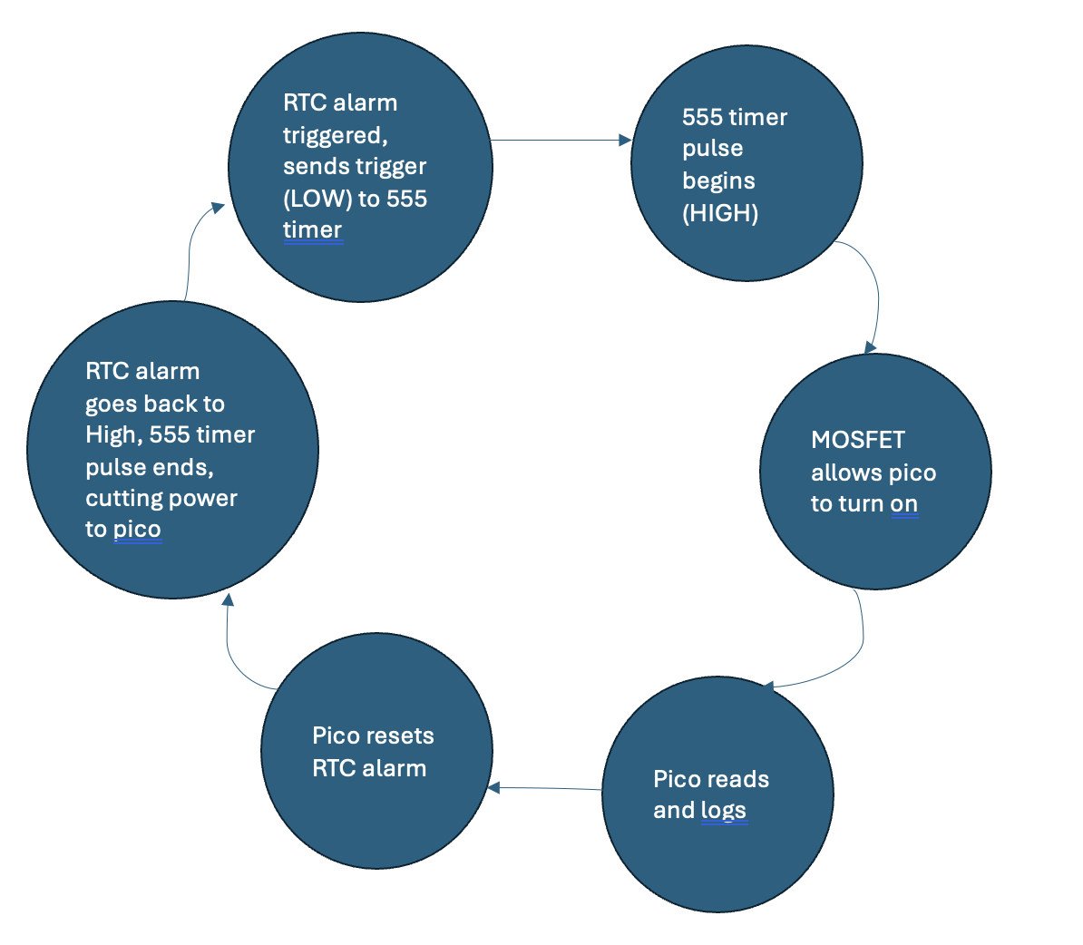
Figure 1. Logging device process for powering the pico
The reading device can be plugged into the jack on the logging device to read data. The reading device has a display, an onboard battery, an on-off switch, and charging cable.
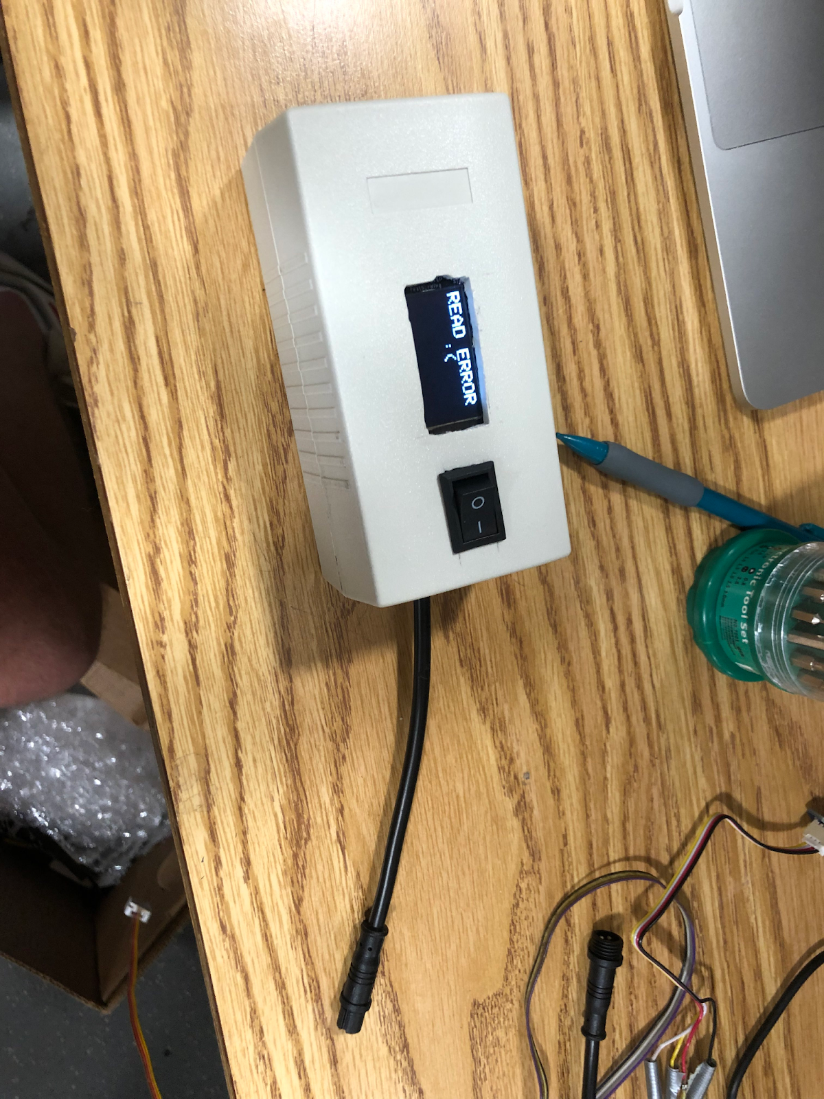
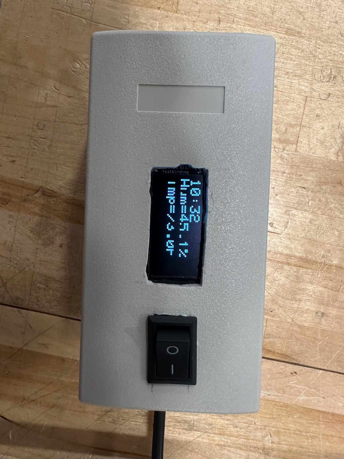
Figure 4: Reading device V1 with display (text looks a little weird when photographed, normal in person)
What parts are involved and why, how do they fit together, why?
Reading device
- Feather RP2040 and Display:
- A feather RP2040-based device with a screen that reads data from the EEPROM and can display it in real time for the beekeeper.
- Cables: Adafruit waterproof 4-wire cables
- Makes the I2C connection between logging device and reading device
- I2C hot-plug module
- we haven’t done anything with this, but it might be a good idea to use this for the connection between reading and logging device, because I2C isn’t meant to be hot-plugged.
- Enclosure for V1
- We should 3D print something for this later, this is too expensive and hard to use. Had to cut some holes in it.
- Feather reading script
- Reads from the EEPROM and displays on the display. See above notes for pico logging script.
Logging Device: The logging device is a raspberry pi pico on a custom PCB. The PCB is designed so that a RTC will send an alarm signal at a selected interval which will turn the pico on and allow the pico to collect data.
- RPi pico (or pico W)
- Stores data, reads with sensors over i2c
- Chosen because of lower power consumption (~15mA in standard sleep), low cost, and ease of programming with MicroPython. Way easier to setup than all the mess of a pi zero
- See the guide to get started
- Temperature+humidity sensor
- Measures values and is read by the Pico over i2c
- Put a little 3d-printed mesh over this so bees don’t cover it all up with gunk, designed by Matt + Vincent. File for this is in the box.
- Light sensor
- Measures values and is read by pi/pico over i2c
- RTC module (different from last year!)
- Keeps track of time while the pico is off
- Sends alarm signal periodically
- Must be reset by i2c command to turn of alarm signal
- 555 timer
- Creates longer pulse to activate the MOSFET
- Read the datasheet, search for “monostable mode” to understand what the output is
- We chose the CMOS version because that will consume less power than TTL
- MOSFET: FQP30N06L
- Chosen for being logic-level compliant. It can handle high current but we don’t use anything near its limit
- The electronics services shop has a bunch of these you can get for free!!!
- HX711
- Module for reading from the weigh scale. Talk to weigh scale team about this and other parts
- Solar panel, battery, charging board
- Batteries are 18650 with JST PH2 connector that fits into the part in the charging board
- The charging board is really easy to use: just connect panel + battery and plug something into the USB to receive power
- EEPROM chip
- We chose the 24LC256 because it can be read/written over i2c, which we are already using. It has more than enough space to store the most recent data.
- Starting at page 10 in the datasheet, there is info about commands to read/write to it. Important to note that you can only write up to 64 bytes with one command due to maximum “page” size.
- Brick and screws
- To attach the device to a hive, we need something that will shed water (see notes about this below) and won’t get blown off by the wind. This led to the setup in Figure 2.
- Code: We work with the wireless communication team to combine our code together. The code structure of wireless team is quite different from our team, so we need to make several changes in order to combine our code:
- We need to translate our code from micro python into circuit python. We are currently working on translating logging code for TMG sensor into circuit python and here are some points we need to be aware of: I2c can only be initialized one through out the code We need to lock and unlock the i2c bus before and after reading from sensors The reading and writing function for circuit python is different from micro python. We changed the writing part but did not reach the reading part.
- We need to follow the structure provided by wireless team. This can be found in the wireless team’s GitHub in example module. https://github.com/duskusus/WaggleNetWireless. Their idea is to make each sensor in to a class and collect data from sensors one by one. Their structure contains the “setup(self):” set up function which establish i2c connection. This can only be initialized once. Initialize the sensors with data. “poll(self)” contains the function that polls data from sensors. We did not changed the read data function of this part. We probably need to add lock/unlock function in this part.
Logging Device Enclosure [ADD CURRENT FILE]: a 3D hollow box that will hold the battery, solar power manager, and logging device PCB. It’s designed so its holes align with those on the brick, so it can mount to it via long screws, and prevents condensation from forming on the parts/damage to the parts. This enclosure uses heat inserts for mounting the parts inside and for connecting the long screws to the brick.
For each part, who knows the most about it?
Logging device enclosure: Nandini
Logging device PCB: Norbert, Anjali
Reading device: Cameron
Logging device code: Gloria
Where are your parts and files stored?
WN Box has up-to-date files for PCB, logging device code, enclosure, reading device code.
Our physical parts are in the “Data Collection” box.
Reading device parts are in an Adafruit box within our Data Collection Box.
What is something you considered doing but you abandoned / that didn’t work out / that you replaced?
How the RTC alarm worked: The PCB was designed with the idea that the alarm signal goes low and then back to high on its own, thinking that this short pulse would trigger the 555 timer. But actually the alarm signal does not return to high until the alarm flag is reset with an I2C command, which the pico will have to do. So we might not actually need the 555 timer anyway.
- Old PCB Document with incorrect understanding of RTC alarm https://www.wagglenet.org/wp-content/uploads/2024/01/PCB-Information.pdf
We somehow busted GP8 and GP9 on one pico. Everything else was normal on it.
We also realized that our pullup resistances R6 and R7 on the PCB were too high(100kOhms) for them to be effective so we replaced them with 10kOhm resistors.
PCB Debugging: Needed to test alarm signals as explained above. Additionally, required testing of the ability to power the pico with the solar panel and turning the pico on utilizing the signal from the RTC alarm.
What changed have you made since last year?
- New PCB for logging device
- Integrated weight scale code with ours, so the logging device can read from an HX711, and there’s space for the HX711 on our PCB.
- Software: the logging code was cleaned up to be more modular, easier to read
- We made some slight modifications to the ds3231.py code specifically in the set_time function to work to solve the issue with the “RTC not found” error message.
- Prototyped the reading device
What skills does a noob need to contribute to your project?
- Understanding of circuitry
- Python
- KiCAD
- Oscilloscopes, logic analyzer useful
- CAD and 3D printing
What are we still working on / need to work on soon:
- Updating/reprinting the logging device enclosure with mounting holes & allocated space for the components being stored within it.
- We need to determine whether the pico being powered with Vbus instead of Vsys is a problem or not. Additionally, we can further test the functionality of the PCB itself by transferring it onto a breadboard and ensuring it works as intended with an oscilloscope at the major test points.
- Reading device needs a better format, UI. Battery indicator would be good too. Basically we need to do some market research. Also need to make a 3d-printable enclosure for this; the one we have is not the cheapest and doesn’t look great / isn’t easy to use
- Integrating wireless module onto our PCB: the adafruit breakout we’ve been using is just the actual radio module plus some level shifters, so we could save $10/device by putting the module directly on our PCB. Cameron has notes on how we need to wire this onto the pico – mainly it’s just SPI connections or power, but then you have to connect an antenna which might need to be a certain length or impedance or something
- See this file for the plan!!!
- Making sure there are the right number of pullups on the i2c lines to avoid issues
- Next version of the PCB should have:
a.Proper MOSFET footprintb. Fix weird angle on 555- c. LoRa module (talk to Ted)
- Digikey link – buy this one?
- Need to make custom part and footprint for LoRa Module
- See notes for what is really needed
- Wider spacing for the 3.3V LDO bc they’re really close together – just a different footprint probably
- Mounting holes
- 10K pullups, not 100K
- Code:
- Debug the “poll(self)” part of the TMG sensor
- create class for other sensors